Dc Power Supply Design Using Flyback Converter
How to Design a Flyback Converter in Seven Steps
Miguel Ametller

Get valuable resources straight to your inbox - sent out once per month
We value your privacy
Introduction
Of the many converter topologies around today, the flyback topology is one of the most frequently used. Although simple, this converter design offers great advantages for certain applications. New, more complex topologies have surfaced in recent years, but flyback converters remain a popular design choice.
These switch-mode power converters offer competitive size, cost, and efficiency ratios in the low- to mid-power range (about 2W to 100W). A flyback converter's operation is based on a coupled inductor, which aids in power conversion while isolating the converter's input and output. The coupled inductor also enables multiple outputs, which makes flyback converters the standard for a wide variety of applications.
Flyback Converter Operation
Flyback converters are made up of the same basic elements as most other switching converter topologies, but the differentiating element of a flyback converter is its coupled inductor, which isolates the converter's input from its output (see Figure 1).

Figure 1: Flyback Converter Schematic
A flyback converter has two signal semi-periods: tON and tOFF, which are named after (and controlled by) the MOSFET's switching states.
During tON, the MOSFET is in the on state, and current flows from the input through the primary inductor to linearly charge the coupled inductor. During tOFF, the MOSFET is in the off state, and the coupled inductor begins to demagnetize through the diode. The current from the inductor charges the output capacitor and powers the load.
Flyback Converter Design and Component Selection
There are many important design decisions and tradeoffs involved in designing a flyback converter. The following sections will go through each step in the design process for a simple flyback converter. Figure 2 shows the design flow that will be followed.
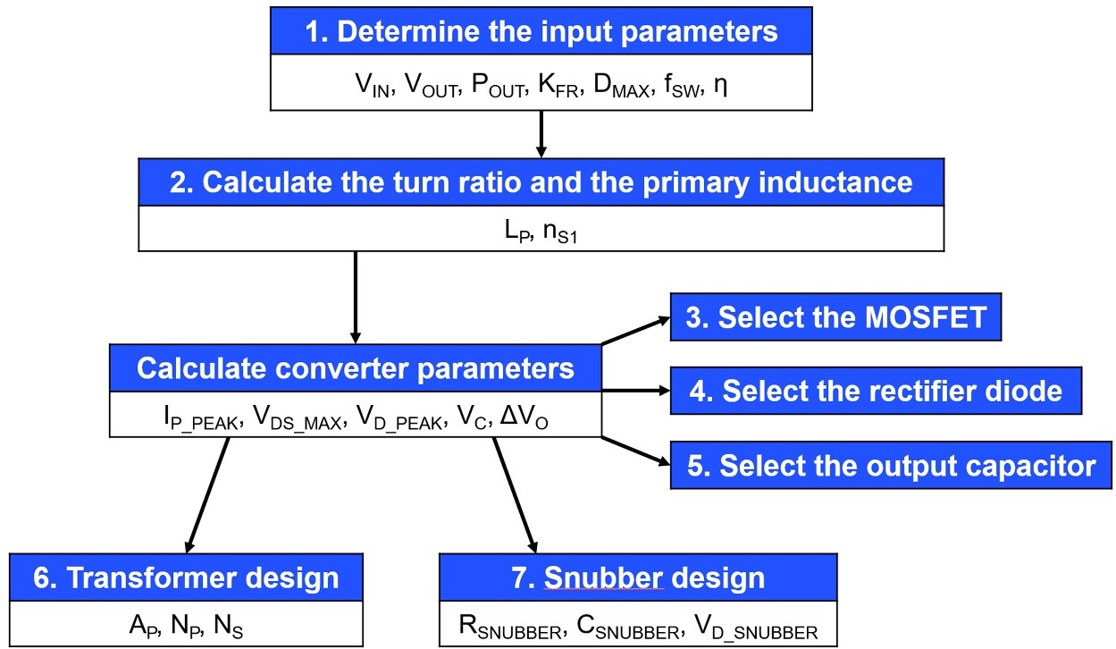
Figure 2: Design Flowchart for a Flyback Converter
Flyback Converter Design Process and Calculations
Step 1: Design Inputs
Design inputs are either defined by the end application or selected by the designer. These parameters include, but are not limited to, the input and output voltages, power, ripple factor, and operation mode. Table 1 shows a summary of the design inputs for the circuit discussed in this article.
| Design Input | Value |
| Input voltage (VIN) | 32V to 78V |
| Output voltage (VOUT) | 12V |
| Output current (IOUT) | 1A |
| Operation mode | DCM |
| Ripple factor (KFR) | 1 |
| Maximum duty cycle (DMAX) | 0.5 |
| Switching frequency (fSW) | 160kHz |
| Estimated efficiency (η) | 80% |
Table 1: Design Input Summary
Discontinuous conduction mode (DCM) was selected for this application due to its increased stability and higher efficiency. This means that the solution's ripple factor is 1.
The maximum duty cycle is fixed at 50% to minimize stress and to equally utilize the MOSFET and the diode. The switching frequency was chosen to be 160kHz.
To make the calculations more realistic, the converter's estimated efficiency is defined. The efficiency is estimated to be relatively low (about 80%), as this is a common value for low-power flyback converters.
Given all these inputs, the designer must choose a controller IC that meets all of the initial requirements. MPS's MP6004 was used for this example. The MP6004 is a flyback controller that only operates in DCM. It also features primary-side regulation, which reduces the external component count.
Step 2: Calculations to Select the Maximum Primary Inductance
The first design calculation aims to find the maximum primary inductor value. There are many different design methods available, but the converter used for this example always operates in DCM. Calculate the primary inductor value (LP) with Equation (1):
$$L_P = \frac {η \times D_{MAX^2} \times V_{IN\_MAX^2}}{2 \times f_{SW} \times K_{FR} \times P_O} = \frac {0.8 \times 0.5^2 \times 32^2}{2 \times 160 \times 10^3 \times 1 \times 12} \approx 53μH$$
The worst-case scenario occurs when the converter works at full power with a minimum input voltage and maximum duty cycle. By implementing the design inputs in Equation 1, the limit for the maximum inductance is determined to be 53μH.
Next, the required turn ratio (nS1) is calculated. To do so, the same worst-case scenario is applied with a minimum VIN and maximum D. The diode's forward voltage drop is added to make the calculations more precise. Estimate nS1 with Equation (2):
$$n_{S1} = \frac {V_{IN\_MIX} \times D_{MAX}}{(1- D_{MAX}) \times (V_O + V_D)} = \frac {32 \times 0.5}{(1-0.5) \times (12 + 0.7)} \approx 2.5$$
Step 3: MOSFET Calculations
The next step is to select the right MOSFET for the application. To do so, calculate the maximum current and voltage that the switch will have to withstand. Calculate the maximum voltage with Equation (3):
$$V_{DS\_MAX} = V_{IN\_MAX} + \frac {D_{MAX} \times V_{IN\_MIN}}{1-D_{MAX}} = 78 + \frac {0.5 \times 32}{1-0.5} = 110V + 20\% \space safety \space margin = 132V $$
Note that a 20% security margin has been added to VDS_MAX to ensure the converter's safe operation. Estimate the maximum current with Equation (4):
$$I_{P\_PK} = \frac {P_{IN}}{D_{MAX} \times V_{IN\_MIN}} + \frac {D_{MAX} \times V_{IN\_MIN}}{2 \times f_{SW} \times L_{P\_MAX}} = \frac {12 \times \frac {1}{0.8}}{0.5 \times 32} + \frac {0.5 \times 32}{2 \times 160 \times 10^3 \times 53 \times 10^{-6}} = 1.88A $$
Looking at the MP6004 controller specifications, the VDS_MAX for the MOSFET is 180V and the maximum current is 3A. This means that the controller IC can be used safely in this application.
Step 4: Rectifier Diodes Calculations
In this step, the rectifier diodes are assessed. As with the MOSFET, the aim is to ensure that the rectifier diode can handle the maximum voltage and current that it may encounter. Calculate the maximum voltage that the diode can withstand with Equation (5):
$$V_{D1\_{PK}} = V _{OUT} + \frac {V_{IN\_MAX}}{n} = 12 + \frac {78}{2.5} = 43.2V + 40\% \space safety \space margin = 60.5V$$
By adding a 40% safety margin, the maximum reverse voltage is determined to be 60.5V.
Step 5: Output Capacitor Calculations
An estimate is used to determine the value of the output capacitor, meaning the second-order aspects of the circuit are ignored, such as parasitic components and output crosstalk. Estimate the voltage in the capacitor with Equation (6):
$$V_C = {1 \over C} \times \int_0^{T_{SW}} I_C(t)dt = {1 \over C} \times \int_0^{DT_{SW}} I_C(t)dt = {1 \over C} \times \int_0^{DT_{SW}} - I_O(t)dt = {1 \over C} \times [I_O \times t]_0^{D\space T_{SW}} $$
Note that if this equation is evaluated for tON, it can be greatly simplified. Calculate the output voltage ripple with Equation (7):
$$ \Delta V_O = \frac {D \times I_O}{f_{SW} \times C} $$
Next, choose a capacitor value to provide an optimal ripple voltage. In this case, a 250µF capacitor is used, which incurs a 12.5mV output voltage ripple.
Step 6: Flyback Transformer Design and Calculations
The next design step involves the transformer. There are many design decisions involved in choosing a transformer, such as the core material and core shape. When choosing the core material and shape, each option has its own specific advantages. For this example, the commonly used ferrite core in a double E shape was chosen (see Figure 3).
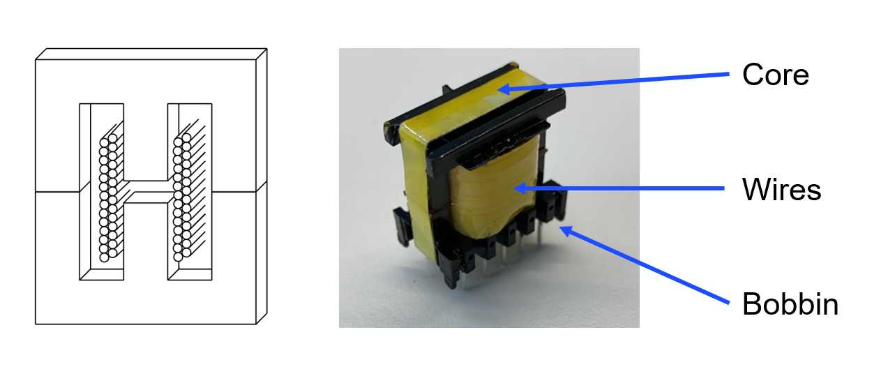
Figure 3: Transformer EE Core and Transformer Main Elements
The method used to calculate the area of the transformer is called the AP method. It defines the total area of the transformer as the product of the winding window area and the area of the core cross-section, where all of the transformer's magnetic flux is concentrated (see Figure 4).
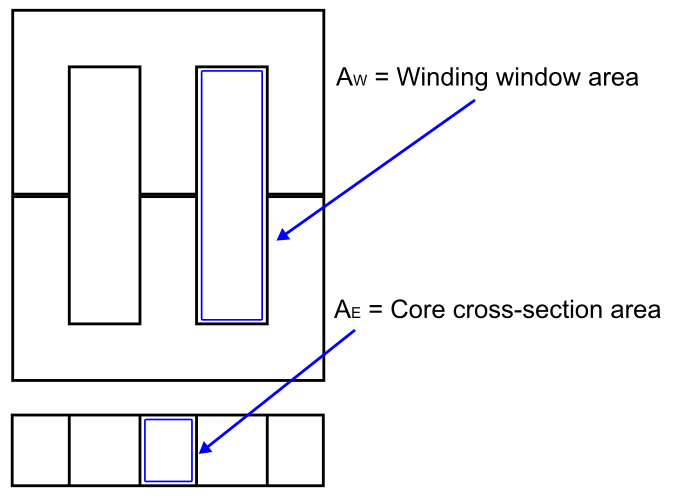
Figure 4: AP Method Areas of Interest
The transformer area can be estimated with Equation (8):
$$A_P = A_E \times A_W [mm^4]$$
Now the method and the design parameters have been defined, a quick set of calculations can be used to design the transformer.
First, calculate the minimum transformer area using Equation (9):
$$A_P = \Biggl( \frac{L_P \times I_{P_{MAX}} \times I_{P_{RMS}}}{B_{MAX} \times 0.0085} \Biggl)^{4 \over 3} \times 10000 = \Biggl(\frac {53μH \times 1.88A \times 0.77A_{RMS}}{0.2 \times 0.0085} \Bigg)^{4 \over 3} \times 10000 \approx 163mm^4 $$
BMAX is typically a defined input parameter; for ferrite cores it is generally between 0.2T and 0.3T. Using the AP method, an EE13 core and a bobbin with a minimum 0.28mm length have been selected.
The maximum primary and secondary turns that can fit in the transformer are then calculated to maintain the turn ratio calculated in Equation (2). Calculate the primary turn number with Equation (10):
$$ N_P = \frac {L_M \times I_{PK\_MAX} \times 10^6}{B_{MAX} \times A_E} = \frac {53μH \times 1.88A \times 10^6}{0.2 \times 20.1mm^2} \approx 25$$
Estimate the secondary turn number with Equation (11):
$$N_S = {N_P \over 2.5} = 10$$
The auxiliary winding turn number is calculated following the same methodology as the secondary output turn number, resulting in NAUX = 5.
Step 7: Snubber Design and Calculations
The last step of the design process is to find the snubber values. This circuit helps to mitigate the voltage spikes that occur due to ringing between the transformer's leakage inductor and stray capacitances in the circuit at the switching node. Without the snubber, the voltage spikes add noise and can even cause MOSFET breakdown. Figure 5 shows a flyback converter with a snubber circuit.
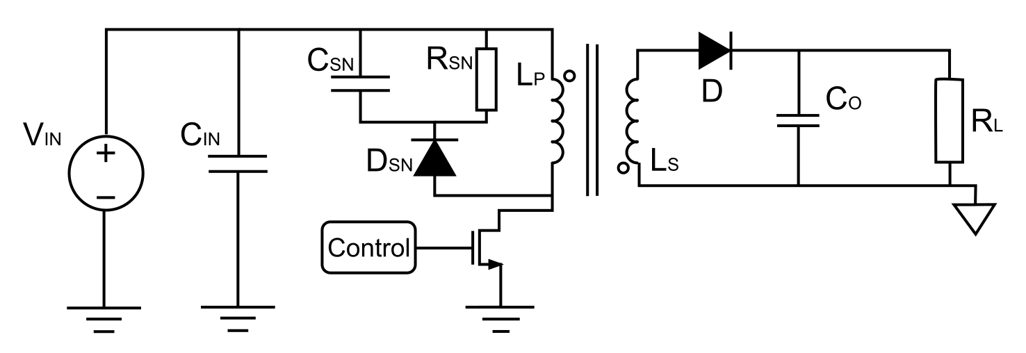
Figure 5: Flyback Converter with an Input Snubber Circuit
For the snubber, the design process is comprised of three stages. First, the leakage inductance is estimated to be about 2% of the primary inductance. Then, a maximum snubber capacitor voltage ripple is set to 10%. Then the values for the snubber components can be estimated.
Calculate the maximum capacitor voltage with Equation (12):
$$V_{C(MAX)} = V_{DS(MAX)} \times 0.1 + \frac {D_{MAX}}{1 - D_{MAX}} \times V_{IN(MIN)} = 132V \times 0.1 + {0.5 \over 1-0.5} \times 32V = 45.2V $$
Estimate the power in the snubber resistor with Equation (13):
$$P_{R_{SNUBBER}} = \frac {I_{P(PEAK)}^2 \times L_{LEAK} \times f_{SW}} {2} = \frac {(1.88A)^2 \times 1.06μH \times 160kHz}{2} = 0.3W$$
Using the power as a limiting parameter, calculate the snubber resistor value with Equation (14):
$$R_{SNUBBER} = \frac {(V_{C(MAX)})^2} {P_{R_{SNUBBER}}} = \frac {(45.2V)^2}{0.75W} = 2.72kΩ$$
Estimate the value of the snubbing capacitor with Equation (15):
$$C_{SNUBBER} = \frac {1}{\Delta V_C \times R_{SNUBBER} \times f_{SW}} = \frac {1}{10\% \times 2.72kΩ \times 160kHz} = 23nF$$
Lastly, calculate the maximum voltage across the snubber diode with Equation (16):
$$V_{D_{SNUBBER}(PEAK)} \approx 1.2 \times V_{DS(MAX)} = 1.2 \times 132V = 158.4V$$
Final Design
After calculating the values for all of the converter components, the MP6004 regulator can be paired with its external components to establish a fully functional flyback DC/DC converter.
Note that this circuit includes the components that have been previously mentioned, such as the primary inductor (LP), the auxiliary inductor (LP2), the output capacitor (which is made up of the parallel addition of C2A, C2B, and C2C for improved frequency response), the rectifier diode (D1), and the snubber circuit.
Figure 6 shows the circuit's final design, as well as new components, such as the MP6004's primary-side controller. The controller includes the MOSFET switch and all of its related circuitry, as well as some additional components for noise filtering.
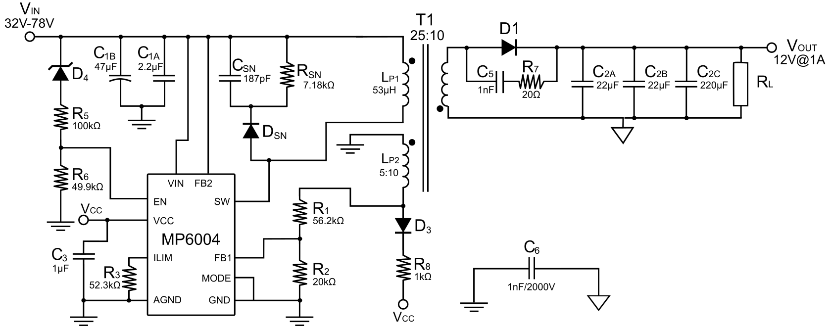
Figure 6: Final Design Circuit Schematic
Conclusion
This article used the MP6004 from MPS to demonstrate how to design a flyback converter in eight simple steps. Though there are many more things to consider before a design is ready for implementation — such as passing EMC tests, control loop design, and component selection — it is important to establish a clear method for calculating and selecting components.
Many design decisions will have significant effects on the overall behavior of the system, so establishing the input design parameters is a crucial first step. These parameters set the constraints for the converter design, and the remaining steps involve selecting values in accordance with these specifications.
_______________________
Did you find this interesting? Get valuable resources straight to your inbox - sent out once per month!
Technical Forum
Get technical support
Dc Power Supply Design Using Flyback Converter
Source: https://www.monolithicpower.com/en/how-to-design-a-flyback-converter-in-seven-steps
0 Response to "Dc Power Supply Design Using Flyback Converter"
Post a Comment